The short answer
Reduce backscatter by moving the lights away from the camera's axis before adding brightness, because particles lit directly in front of the lens bounce light back into it. Then dim to the lowest level at which the pilot can still do the job, testing one change at a time against a fixed target.
- Decide first what the pilot must see, and from how far away.
- Lock the camera's exposure while you test, or automatic exposure hides the change.
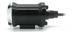
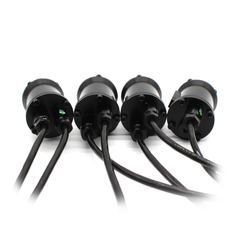
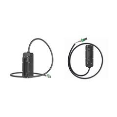
- Blu-Sub's 1,500-lumen light runs on 10–28 V at up to 17 W, with PWM dimming.
ROV lighting: reducing backscatter before adding more lumens
More light also lights up the particles in the water, not only the thing you are inspecting. Choose ROV lights on camera-to-target distance, where the lights sit, beam coverage and dimming. Lumens are the last thing to compare.
Define what the operator must see
Write down exactly what the pilot has to see: a marking to read, a connector to identify, marine growth, or a surface to document. Note the target size, the working distance, and whether the image is for piloting or close inspection. A wide piloting view and a close inspection view may need different lighting.
For example, 'read a sample ID plate at 0.5 m in water like the site's' is a brief you can test. It is only an example. Keep the same plate for every test so you compare layouts fairly.
Move the light away from the camera axis
Backscatter is light bounced back into the camera by particles in the water. Lighting less of the water directly in front of the lens usually improves the picture. Blue Robotics' assembly guidance suggests mounting lights outside the frame to cut backscatter, at the cost of less protection for the lights.
On a custom frame, keep the spacing and aim adjustable while you develop it. Light the target without crossing both beams right in front of the lens. Check the camera's full tilt range, shadows from the frame, and any manipulator that comes into view. No single spacing works for every beam and every kind of water.
Dimming and beam coverage matter
Start the in-water test at low brightness and turn it up while you watch target detail, glare from particles, and bright surfaces washing out. Keep the camera settings fixed where you can, or automatic exposure will hide the effect of moving or dimming a light.
Check beam coverage at the working distance, right out to the edges of the camera view. A bright centre with dark corners may be fine for a small inspection target and poor for piloting. Try one light first, then the pair or array: more beams don't always give a better picture.
A Blu-Sub electrical example
Blu-Sub lists its 1500-lumen dimmable light with a 10–28 V input, 17 W maximum power, approximately 90-degree beam and PWM dimming. The documented PWM level is 3.3–5 V with a 1100–1900 microsecond control range. Confirm the supplied revision and wiring documentation before connection.
As a rough load estimate, two 17 W lights draw 34 W at full power. On a 24 V supply that is about 1.42 A (34 / 24), before the rest of the system and the losses in distribution. This tells you nothing about how far you will see underwater.
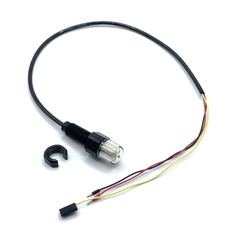
Blu-Sub specifies a common ground between the light's supply and the PWM source. Put power, signal and cable routing on the installation drawing, and check that your controller output can produce the signal. Check the cable terminations and the depth rating of the assembly separately from the lighting test.
Use a repeatable in-water comparison
Put the same target at marked distances. For each clip, note the light spacing, aim, brightness setting, camera exposure and water conditions. Change one thing at a time. Judge each clip on whether the pilot could do the job; the brightest clip is often not the best.
Repeat the best layout with the camera tilted and with shiny surfaces nearby, as there will be on site. If you can, check the picture with the vehicle moving as well as still. Keep an example image of the quality you need with the project specification, so sign-off doesn't rely on memory.
Prepare a lighting enquiry for your ROV
Send the camera model, the target and working distance, water conditions, mounting space, supply voltage, control interface and operating depth. A photo or sketch of the front of the vehicle helps most, because it shows where shadows will fall and how much room there is to adjust.
Look at subsea lighting and underwater cameras together. What matters is the picture from the assembled vehicle, so leave time for a test in the water before you fix the mounts.
Sources.
- Blue Robotics: light placement and the protection/backscatter trade-off. We cite it for the mounting principle; it says nothing about mixing brands.
- Blu-Sub: dimmable underwater LED light specifications and control wiring.
Published 5 September 2026. Last revised 25 September 2026. Corrections to sales@vebixautomation.com.
Planning an underwater inspection camera?
Send us the camera, what the pilot needs to see, and a mounting sketch. Ask for a quote on Blu-Sub lights and cameras.
More on underwater robotics
- Underwater and ROV thrusters in IndiaBlu-Sub and Blue Robotics underwater thrusters for ROVs, AUVs and USVs, with prices in rupees and delivery across India included.
- How to choose an underwater thruster for an ROVHow to choose an underwater thruster for an ROV by thrust, voltage, depth rating, ESC, rotation and mounting.
- How to size an underwater thruster for an ROVSize ROV thrusters from drag, target speed and vectoring angle. Worked method for thrust per unit, thruster count and the margin real vehicles need.
- Designing a 300-metre ROV propulsion systemPropulsion design for a 300-metre ROV: thruster count and layout, bus voltage, tether losses, sealing and the effect on buoyancy.
- Aluminium versus acrylic subsea enclosuresAluminium and cast acrylic subsea housings compared on depth rating, optical access, heat, servicing and cost.
- Selecting a subsea enclosure for marine research payloadsHow to choose a subsea enclosure, end caps, seals and penetrators for research payloads, and how to test them before fieldwork.
/LR/thumb/Blu-Sub_DimLight_LR_01.jpg)