
The short answer
Choose a telemetry radio from a link budget rather than the advertised range, and fix the band first: 433 MHz and 915 MHz radios are separate part numbers that can't talk to each other, and national regulation decides which band you may use. Better antennas and placement usually add more margin than more transmit power.
- Telemetry is one of three radio links, separate from RC control and video.
- Usable MAVLink throughput is always lower than the air data rate.
- Keep antennas clear of carbon structure, ESCs and the power harness.
How to choose a UAV telemetry radio: data rate, range and ground-station compatibility
An advertised range describes a radio in conditions your aircraft will never fly in. The link you get depends on the margin left after your installation has taken its share, and you can work that out before you order.
Three radio links, and this guide covers one
An unmanned aircraft usually carries three radio links, and mixing them up wastes money either way. The RC control link carries pilot input and has to be the most robust. The video link carries the largest data rate and tolerates errors well. The telemetry link is this article's subject: a bidirectional data link carrying MAVLink between the autopilot and a ground control station.
Write down what the telemetry link has to do before you compare radios. Live parameter tuning, uploading missions in flight and a moving map with a useful update rate need far more than a status heartbeat and a position every second. Payload data is another requirement again, and usually belongs on a different radio.
Then write the range as two numbers: the distance at which the link must be reliable, and the distance at which losing it is only an inconvenience because the aircraft carries on and comes back. A telemetry link that drops at the far end of a survey line is a nuisance. A control link that drops is an incident. Specify them separately.
Advertised range and installed range are different numbers
A published range is measured in line of sight, with good antennas, no airframe in the way and no interference. That is fine for comparing radios, but it doesn't predict how your aircraft will do. For that you need a link budget, which takes a couple of minutes on paper.
Free-space path loss in decibels is FSPL = 20 log₁₀(d) + 20 log₁₀(f) + 32.44, with distance in kilometres and frequency in megahertz. At 915 MHz over 5 km: 20 log₁₀(5) = 13.98, 20 log₁₀(915) = 59.23, so FSPL = 13.98 + 59.23 + 32.44 = 105.65 dB.
Now spend it. Take a 100 mW transmitter, which is +20 dBm. Lose 1 dB in the aircraft's antenna cable, gain 2 dBi at the antenna, lose the 105.65 dB of path loss, gain 2 dBi at the ground antenna and lose another 1 dB of cable: 20 − 1 + 2 − 105.65 + 2 − 1 = −83.65 dBm arriving at the receiver.
Now the receiver. Holybro publishes the SiK V3's sensitivity as −121 dBm at a 2 kbps RF data rate and −105 dBm at 64 kbps, and 64 kbps is the default. The same radio on the same link therefore has a 16 dB spread in sensitivity, decided by nothing but how fast you asked it to signal.
At the default 64 kbps the margin is −83.65 − (−105) = 21.4 dB. Turned down to 2 kbps it is 37.4 dB: the same hardware and antennas, with 16 dB more margin in exchange for less throughput. That is the most useful trade on this page, and you can make it from a settings screen after the aircraft is built.
Neither margin is spare. It has to pay for airframe blockage, antenna orientation, terrain and interference, and the next section lists what takes its share.
What eats the margin, and why more power is the last resort
Airframe blockage. A carbon-fibre airframe is conductive and reflective. An antenna mounted where the fuselage sits between it and the ground station during a banked turn can lose far more than the few decibels people expect.
Polarisation mismatch. Two linearly polarised antennas at right angles to each other lose a lot of signal. An aircraft banking through 90° does exactly that to a vertical whip on the ground.
The Fresnel zone. Line of sight isn't enough; the signal needs clear space around the straight line too. A link that works at 100 m altitude and fails at 20 m over the same ground usually has this problem, and the radio is fine.
Interference. Other people use the same bands. A site that is quiet on a Sunday morning may be busy on a weekday.
Going from 100 mW to 1 W adds 10 dB, and it is often the most expensive way to get it: it costs current and heat, and in a power-limited band it may not be legal. Better antennas, better placement and a shorter cable are usually cheaper, so try those first. Also, raising power at one end only improves that direction, and the link is only as good as its weaker direction.
Frequency band: confirm what you are allowed to use
Holybro sells the SiK Telemetry Radio V3 as separate 433 MHz and 915 MHz part numbers, and they don't mix: a 433 MHz air unit won't talk to a 915 MHz ground unit at any range. Both ends must be on the same band. This mistake usually turns up when someone orders a spare a year later.
National regulation decides which bands and transmit power you may use. Confirm the permitted allocation and power limit for your country and for the class of operation before ordering, and record the answer in the project file. In India that is a question for the national spectrum authority and, where the flight is not purely indoor, for the applicable UAS rules.
The physics is simple enough to reason about. Lower frequencies lose less over the same distance and get through obstructions better; higher frequencies allow smaller antennas and usually more bandwidth. That is why a long-endurance survey aircraft and a short-range inspection quadcopter can sensibly end up on different bands.
Data rate: the number to specify is the one you need
Two different rates get mixed up all the time. The air data rate is what the modem signals at. The usable throughput is what your MAVLink stream gets after error correction, framing and the return path take their share, and it is always lower.
Specify from what the ground station needs. A basic status and position display asks little. A full parameter download, a mission upload in flight, or fast attitude data for tuning asks a lot, and on a weak link these don't fail cleanly. You get a lagging display, a parameter list that never finishes, and a link that seems fine until you need it.
Understand the trade before you choose: a lower air data rate improves receiver sensitivity, and so range, at the cost of throughput. A radio that reaches its advertised distance at its lowest rate won't reach it at its highest. Decide which your mission needs more, and set both ends to match.
Antenna installation is part of the specification
Mount the antenna clear of carbon structure and away from the ESCs and power harness, with strain relief on the connector. A coax pigtail flexing against a frame edge for fifty flights will start dropping the link now and then, which is much harder to diagnose than a link that fails outright.
Keep the cable short. A thin pigtail loses real signal at these frequencies, and every decibel it loses comes off the margin you calculated. Line up the aircraft and ground antennas for the attitude the aircraft flies in most, and check what happens in a hard turn.
Never power a radio without its antenna connected. On the ground, height matters more than power: a ground antenna on a mast clears obstructions and the Fresnel zone in a way extra transmit power can't.
Ground-station compatibility and what to send with an enquiry
Check three connections. The aircraft side: which autopilot port, its connector and pinout, and the serial baud rate configured for it. The ground side: how the radio reaches the computer or tablet — USB, serial, or a network interface — and whether that host has a driver and a port. The software: which ground control station, and whether it is being used with PX4 or ArduPilot.
We list radios as single units and as pairs. Buy a pair for your first aircraft. Buy singles to add a second ground station, keep a spare, or fit a second aircraft to an existing ground unit. Every unit that has to talk to another must match on band and firmware settings.
Send us the autopilot and port, the ground station software and computer, the distance and environment you will fly in, the band you are allowed to use, and whether you need a single or a pair. That is enough for us to shortlist radios and to catch a mismatch before anything ships.
Telemetry radios we sell
Both ends of a link must be on the same band, so order a pair or two matching singles.
| Radio | Holybro SKU | Band | Transmit power | Supplied as |
|---|---|---|---|---|
| SiK Telemetry Radio V3 100 mW 433 MHz | 17012 | 433 MHz | 100 mW | Single |
| SiK Telemetry Radio V3 100 mW 915 MHz | 17013 | 915 MHz | 100 mW | Single |
| SiK Telemetry Radio V3 1 W 915 MHz | 17030 | 915 MHz | 1 W | Single |
| SiK Telemetry Radio V3 1 W 915 MHz | 17031 | 915 MHz | 1 W | Pair |
| Microhard P900 | 17035 | 900 MHz band | — see specification | Single |
| Microhard P900 | 17036 | 900 MHz band | — see specification | Pair |
| Microhard P400 | 17037 | 400 MHz band | — see specification | Single |
| Microhard P400 | 17038 | 400 MHz band | — see specification | Pair |
For the Microhard P400 and P900, output power, sensitivity and data rates are in Microhard's own documentation. Check the permitted band and transmit power with your national regulator before ordering.
Parts in this guide.
Check the exact variant and revision before you order.
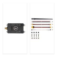
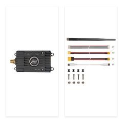
SiK Telemetry Radio V3 1 W 915 MHz (Pair)
Both ends, matched band and power. SKU 17031.
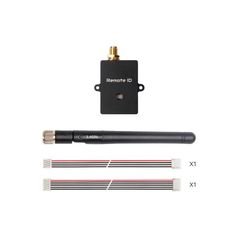
SiK Telemetry Radio V3 100 mW 433 MHz
433 MHz single unit. SKU 17012.
Microhard P900 Pair
900 MHz band pair. SKU 17036.
2.4 GHz / 900 MHz dual-band T antenna
IPEX1 antenna option. SKU 32010.
All telemetry radios and antennas
The full range, in every band, as singles and pairs.
Sources.
- Part numbers, band, transmit power and single-or-pair supply format for the SiK Telemetry Radio V3, Microhard P900 and P400 ranges from the manufacturer's published specifications.
- Free-space path loss: FSPL(dB) = 20 log₁₀(d km) + 20 log₁₀(f MHz) + 32.44. Receiver sensitivity figures are Holybro's.
- SiK telemetry radio V3 (accessed 2026-09-07)
- PX4 companion-computer connection (accessed 2026-09-07)
Published 7 September 2026. Last revised 25 September 2026. Corrections to sales@vebixautomation.com.
Specifying a telemetry link?
Send us your autopilot and port, ground station software and computer, the distance you need and the band you are allowed to use. We will reply with a shortlist of parts that work together, including antennas and cables. Ask for a quote.
More on drones and autopilots
- Pixhawk 6C, 6C Mini, 6X or 6X Pro: which flight controller should you choose?Compare Holybro Pixhawk 6C, 6C Mini, 6X and 6X Pro: integrated versus separate baseboard, case and variant options, and an exact-SKU checklist to order from.
- Analog, digital or DroneCAN: choosing a Pixhawk power moduleMatch a Pixhawk power module to its controller: analog sensing, I2C digital sensing and DroneCAN, plus voltage, current and wiring checks before ordering.
- Building an AI research drone: integrating a companion computer with PixhawkFit a companion computer to a Pixhawk: who does what, serial and Ethernet links, separate power, cooling and a bench-test checklist.
- Drone GPS, RTK and dual-antenna heading: which do you need?Choose drone GNSS by positioning and heading needs. Compare standard GPS, RTK corrections and dual-antenna yaw, with a Holybro sourcing checklist.
- Choosing a drone ESC: PWM, DShot, telemetry and programming compatibilityChoose a drone ESC by control protocol, telemetry path and firmware family: PWM versus DShot, BLHeli-32 versus AM32, configuration tools and troubleshooting.
- Holybro S500, X500 V2 or X650: choosing a drone development kit for researchCompare Holybro S500 V2, X500 V2 and X650 drone kits: wheelbase, included propulsion and avionics, frame versus ARF versus development format.
/LR/thumb/Holybro_2_4GHz_900MHz_Dual_Band_T_Antenna_IPEX1_01.jpg)




/LR/thumb/Holybro_SiK_Telemetry_Radio_V3_1W_915MHz_Pair_01.jpg)
/LR/thumb/Holybro_SiK_Telemetry_Radio_V3_1W_915MHz_Single_01.jpg)
