The short answer
Optical flow, lidar and visual odometry all measure movement rather than position, so their error grows the longer you fly. For indoor and low-altitude work, the setup that holds position is the autopilot's IMU plus a downward range sensor plus an optical flow sensor, over a textured floor at modest height. Add visual odometry only when the mission needs a full pose.
- A downward range sensor measures height above the surface, not altitude.
- Optical flow fails over featureless floors, still water and in low light.
- Build and test in order: range sensor, then flow, then vision.
Indoors, under a bridge, inside a tank or between tall buildings, the GNSS position simply stops. The sensors sold as the answer measure four different things, and none of them is a position. Choosing between them starts there.
None of these replaces a position fix
This misunderstanding wastes more money than any other. A GNSS receiver gives an absolute position. It is wrong by some amount, but the error doesn't grow the longer you fly. Everything in this article is a relative measurement, a rate or a change since the last frame, and adding up relative measurements over time drifts without limit.
No amount of engineering removes that; it is how these sensors work. So the realistic goal for a GPS-denied system is to hold position well enough, for long enough, to do the job, and to know what happens when the estimate gets worse. A quadcopter holding station indoors for a ten-minute inspection is a solved problem. One flying a repeatable surveyed path through a building for an hour on the same sensors is not.
So write the requirement as a time and a tolerance before comparing parts. Hold within a metre for one battery, indoors, over a textured floor is a specification. Works without GPS isn't.
What each one measures
A downward range sensor, a lidar or time-of-flight module, measures the distance to whatever is directly below the aircraft. That is height above the surface, which is different from altitude: fly over a table and the reading drops by the table's height. It is the most reliable of these measurements, and the most modest.
An optical flow sensor measures how fast the image below it is moving, as an angle per second. On its own that isn't a velocity: turning on the spot produces flow without any movement, and the same angular rate means a slow drift at one metre and a fast one at ten. It becomes a horizontal velocity only when combined with height from the range sensor and attitude from the autopilot's gyroscopes. You need optical flow and a range sensor together. They are two halves of one measurement.
Visual odometry, including the visual-inertial kind that runs on a companion computer, estimates how the full pose changes between camera frames, so it gives movement and rotation as well as velocity. It can do far more, and it asks far more: processing power, calibration, and a scene with enough lasting detail to track.
The autopilot's inertial measurement unit already measures acceleration and rotation rate. It drifts fastest of all, which is why the other sensors exist: each one corrects the IMU's estimate before it wanders too far.
Where each one fails: it depends on the site
Optical flow fails over surfaces with no texture: a clean concrete slab, still water, fresh snow, a polished factory floor. It fails in low light, because like any camera it needs exposure. It gets worse as the aircraft climbs past the range sensor's reach, because the velocity is then scaled by a height the aircraft no longer knows.
Time-of-flight range sensors have the opposite surface problem. They misread surfaces that absorb or scatter the beam, and bright sunlight on a shiny floor can blind them. Over vegetation, the reading may come from the canopy one moment and the ground the next.
Visual odometry fails in repetitive scenes, such as a corridor of identical panels, because it can't tell which feature is which between frames. It fails with fast movement that blurs the image, and when the scene itself moves: a room full of people, or a boat deck.
The lesson: each sensor fails in predictable conditions. To choose, describe the surface, lighting and movement at your actual site and rule sensors out on that basis. Headline specifications won't tell you.
A stack that works, and the order to build it in
For most indoor and low-altitude work, the practical setup is the autopilot's own IMU plus a downward range sensor plus an optical flow sensor, combined by the flight stack's estimator. That holds position over a textured floor at modest height, and nothing simpler does.
Add visual odometry on a companion computer when the mission needs full pose rather than station-keeping: following a path, mapping, or returning to a particular spot. That is a much bigger integration job, and our companion computer guide covers who does what, how to power it and the bench tests it needs.
Build it in that order and test each stage before adding the next. A common mistake is fitting flow and vision together, finding the aircraft drifts, and having no way to tell which part is at fault. Range sensor first: check it reports a sensible height over your real floor. Then flow: check the reported velocity matches a measured movement. Only then the vision stack.
Whatever you fit, set the failsafe on purpose. Decide what the aircraft does when the estimate degrades (hold, descend or land) and test it by covering the sensor in flight, at a safe height, over ground you are happy to land on.
A bench and flight check that separates the subsystems
1. Range, static. With the aircraft held at measured heights over your actual operating surface, confirm the reported distance matches. Repeat over each surface the mission includes.
2. Range, dynamic. Walk the aircraft over the obstacles it will fly over and watch for step changes. This is where you find that the sensor is reading the top of a workbench.
3. Flow, translation. Move the aircraft a measured distance at a measured height by hand and compare the integrated velocity against the tape measure. Do it over the worst-textured surface on site, not the best.
4. Flow, rotation. Rotate on the spot without translating. Reported horizontal velocity should stay near zero; if it does not, the attitude compensation is not working.
5. Lighting. Repeat step 3 at the lowest light level the site will present. Optical flow degrades before a person notices the room is dim.
6. Failsafe. In flight, at a safe height, occlude the sensor and confirm the configured behaviour happens. This is the test people skip and the one that matters.
Log the estimator's health and innovation outputs the whole time, and keep the logs. "It drifted" is a mystery. "It drifted because flow quality collapsed at 40 lux" is a problem you can fix.
What to send with an enquiry
The surface you will fly over and its texture, the lighting, the height band, the flight duration, whether you need station-keeping or a repeatable path, your autopilot and firmware, and whether a companion computer is already in the design.
Those last two matter more than the sensor choice. Which sensors a flight stack supports, and on which ports, changes between releases, so choose the parts and the firmware together.
Sensors for flying without GPS
The flow sensor and the range sensor are usually fitted together, so read the last column first.
| Product | Sensing element | Measures | Role in the stack |
|---|---|---|---|
| PMW3901 Optical Flow Sensor | PMW3901 | Optical flow — angular rate of image motion | Horizontal velocity, only when combined with a height source and attitude |
| ST VL53L1X Lidar | VL53L1X | Distance, by time of flight | Height above the surface below; also the scale factor the flow sensor needs |
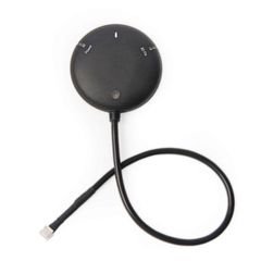
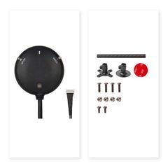
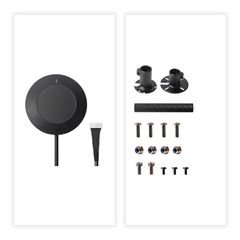
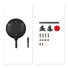
| H-Flow | — not stated in the listing | Optical flow module | Flow and ranging in one module. Confirm the sensing elements and interface against the datasheet |
Range, field of view, minimum light level and firmware support decide whether a sensor suits your site, so ask us for the datasheet for the exact part. Check your firmware's documentation for which sensors it supports, and on which ports.
Parts in this guide.
Check the exact variant and revision before you order.
PMW3901 Optical Flow Sensor
Optical flow. Needs a height source to become a velocity.
ST VL53L1X Lidar
A time-of-flight range sensor, and the height source flow needs.
Holybro H-Flow
Flow and ranging in one module. Confirm the sensing elements on the datasheet.
Pixhawk 6X
The autopilot whose estimator combines these with its own IMUs.
All Holybro sensors
Airspeed, compass, optical flow and ranging.
Sources.
- Sensing element, measurement type and interface for the PMW3901, VL53L1X and H-Flow from the manufacturer's published specifications.
- How PX4 combines a downward camera and distance sensor for velocity estimation: PX4 Guide, Optical Flow.
Published 9 September 2026. Last revised 25 September 2026. Corrections to sales@vebixautomation.com.
Specifying a GPS-denied platform?
Send us the surface, lighting and height you will fly at, the flight time, whether you need station-keeping or a repeatable path, and your autopilot and firmware. We will send back a shortlist of parts that work together. Ask for a quote.
Compare the parts: Drone GPS, GNSS and RTK modules · Airspeed, optical-flow, lidar and compass sensors for drones
More on drones and autopilots
- Pixhawk 6C, 6C Mini, 6X or 6X Pro: which flight controller should you choose?Compare Holybro Pixhawk 6C, 6C Mini, 6X and 6X Pro: integrated versus separate baseboard, case and variant options, and an exact-SKU checklist to order from.
- Analog, digital or DroneCAN: choosing a Pixhawk power moduleMatch a Pixhawk power module to its controller: analog sensing, I2C digital sensing and DroneCAN, plus voltage, current and wiring checks before ordering.
- Building an AI research drone: integrating a companion computer with PixhawkFit a companion computer to a Pixhawk: who does what, serial and Ethernet links, separate power, cooling and a bench-test checklist.
- Drone GPS, RTK and dual-antenna heading: which do you need?Choose drone GNSS by positioning and heading needs. Compare standard GPS, RTK corrections and dual-antenna yaw, with a Holybro sourcing checklist.
- How to choose a UAV telemetry radio: data rate, range and ground-station compatibilityChoose a UAV telemetry radio: data rate against range, a worked 915 MHz link budget, antennas and ground-station fit.
- Choosing a drone ESC: PWM, DShot, telemetry and programming compatibilityChoose a drone ESC by control protocol, telemetry path and firmware family: PWM versus DShot, BLHeli-32 versus AM32, configuration tools and troubleshooting.